

Aim
Flow Control System Using LabVIEW
__________________________________________________________________________________________________________________
Pre-Requisites
__________________________________________________________________________________________________________________
Objectives
__________________________________________________________________________________________________________________
__________________________________________________________________________________________________________________
__________________________________________________________________________________________________________________
__________________________________________________________________________________________________________________
__________________________________________________________________________________________________________________
__________________________________________________________________________________________________________________
Block Diagram of System
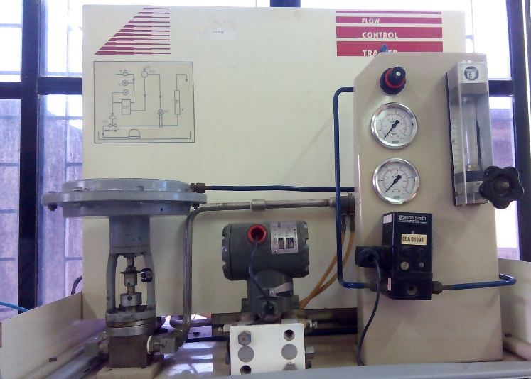
Water is pumped into the tank of flow control trainer. This water enters the orifice through a thin pipe thus creating a pressure difference. This pressure difference is converted to equivalent voltage by the E/P converter. Converted voltage (Process Variable) is acquired through NI myRIO card and given to LabVIEW which compares this voltage with a setpoint voltage. Set point is already set by the user according to desired flow rate. Controller implemented in LabVIEW installed on computer applies an algorithm accordingly to give feedback to the plant. This feedback decides the extent of opening and closing of control valve in the flow control trainer. This effectively controls the flow rate of water.
Actual view of Flow Control Trainer
Schematic of Flow Control Trainer

LabVIEW
LabVIEW (short for Laboratory Virtual Instrument Engineering Workbench) is a system-design platform and development environment for a visual programming language from National Instruments. LabVIEW programs/subroutines are called virtual instruments (VIs). Each VI has three components: a block diagram, a front panel and a connector panel. The last is used to represent the VI in the block diagrams of other calling VIs. The front panel is built using controls and indicators. Controls are inputs – they allow a user to supply information to the VI. Indicators are outputs – they indicate, or display, the results based on the inputs given to the VI. The back panel, which is a block diagram, contains the graphical source code. All of the objects placed on the front panel will appear on the back panel as terminals. The back panel also contains structures and functions which perform operations on controls and supply data to indicators. The structures and functions are found on the Functions palette and can be placed on the back panel. Thus a virtual instrument can be run as a program with the front panel serving as a user interface. The graphical approach also allows non-programmers to build programs by dragging and dropping virtual representations of lab equipment with which they are already familiar.
NI myDAQ
NI myDAQ is a low-cost data acquisition (DAQ) device that gives user the ability to measure and analyze live signals anywhere, anytime. NI myDAQ is compact and portable so user can extend hands-on learning outside of the lab environment using industry-standard tools and methods.
Go to the Simulator tab for performing the simulation.
NOTE: Before running the simulation, download the LVRTE86min.exe file from NI website from the direct link available through “Click here to download LabVIEW Run-Time Engine.(LVRTE)” option. You would require your own user login at NI webpage (if you don’t have already) for downloading the .exe file. Run the .exe file. Then unzip the .zip file.
The plugins are installed in “C:/Programfiles/NationalInstruments/Shared/LabVIEW Run-Time/Current LabVIEW Version8.6/Browser Plugins”.
Copy both the Plugins LV86ActiveXControl.dll (for Internet Explorer), nplv86win32.dll (for Mozilla) and paste in respective browser plugins.
(Eg. C://programfiles/Internet Explorer/Plugins and
C://programfiles/Mozilla Firefox/Plugins)
__________________________________________________________________________________________________________________
__________________________________________________________________________________________________________________
__________________________________________________________________________________________________________________
__________________________________________________________________________________________________________________
__________________________________________________________________________________________________________________
__________________________________________________________________________________________________________________
__________________________________________________________________________________________________________________
1) Electronics Engineering Department
Bharatiya Vidya Bhavan’s
Sardar Patel Institute of Technology
Munshi Nagar, Andheri(W), Mumbai-400058
http://etrx.spit.ac.in/
022-26707440
2) Dr. S.S Rathod
Designation: Professor & HOD, Electronics Engineering Department
Qualification: Ph.D. (IIT Roorkee)
Experience: 18 Years
Expertise: Semiconductor Device Modeling, VLSI Design, Radiation Effects
Email: surendra_rathod@spit.ac.in
3) Prof. P. V. Kasambe
Designation: Assistant Professor
Qualification: M.E. (Pursuing Ph.D.)
Experience: 16 Years
Expertise: Control Sys, Instrumentation, Linear IC, MEMS, IC Technology
Email: prashant_kasambe@spit.ac.in
3) Prof. Reena Sonkusare
Designation: Assistant Professor
Qualification: M.Tech. (Pursuing Ph.D.)
Experience: 16 Years
Expertise: Fiber Optic Communication, Microwave Engineering, VLSI Design
Email: reena_kumbhare@spit.ac.in
4) Tushar Mohan Shingade
M.E.(Electronics and Telecommunication)
Expertise: LabVIEW Programming, MATLAB Programming, scilab Programming,
NI myDAQ, NI myRIO,NI Multisim,Altium PCB designer,Basic webpage design.
Email:tusharshingade100@gmail.com
