
Aim
Characterization of Microheater using LabVIEW
__________________________________________________________________________________________________________________
Objectives
__________________________________________________________________________________________________________________
__________________________________________________________________________________________________________________
__________________________________________________________________________________________________________________
__________________________________________________________________________________________________________________
__________________________________________________________________________________________________________________
__________________________________________________________________________________________________________________
Block Diagram of System
We use an instrumentation amplifier to measure the change in resistance of the microheater due to change in temperature. The microheaters have two coils. One coil is the heater coil and the other is the sensing coil. The varying voltage is given to heater coil and it heats up and the resistance of sensing coil changes. A constant current is given to sensing coil. The voltage across sensing coil is given to instrumentation amplifier. At a time, one microheater is connected in the circuit. The input at inverting terminal of instrumentation amplifier is zero volt. So the differential output obtained from the instrumentation amplifier is voltage across RTD coil of microheater connected in the circuit. This output is acquired on LabVIEW through myDAQ to plot various characteristics.
Depending upon the voltage applied, the temperature of micro-heaters varies. This in turn changes the resistance of the RTD. The resistance of RTD(RT) varies according to following formula:
RT =R0(1 + αT)............................(1)
R30 = R0(1 + αT30)
RT - R30 = R0 α (T - T30)............................(2)
Where,
T = Temperature at which the resistance is heated
α = Temperature Coefficient of Resistance (TCR) of RTD material = 0.002724/°C
R0 = Resistance at 0 °C
RT = Resistance at temperature T °C
The microheater to be characterized is switched on using LabVIEW. The voltage from a DigitalOut pin of myDAQ is given to a constant current source which provides a constant current to the sensing coil of the microheater. No voltage is applied to heater coil to keep it at room temperature. The voltage across sensing coil is given to instrumentation amplifier and is then acquired by myDAQ. Voltage output of amplifier when microheater 1 is connected can be determined by following formula:
Vout = G((I1R1) - 0) ............................(3)
and when microheater 2 is connected,
Vout = G((I2R2) - 0)
Where,
G = Gain of amplifier
I1 = Constant current owing through RTD 1
R1 = Resistance of RTD 1
I1 = Constant current owing through RTD 2
R2 = Resistance of RTD 2
At room temperature,
Vout30 = G(ITR1,30) ............................(4)
Using equation (4) we can find the resistance at room temperature and using equation (1) we can find the resistance at 0 °C.
When heater is heated by applying voltage to the heater coil,
VoutT = G(I1R1T ) ............................(5)
From equation (5), we can find the value of resistance R1 at temperature T. By substituting this value in equation (1), we will get temperature T.
Actual view of Characterization Setup
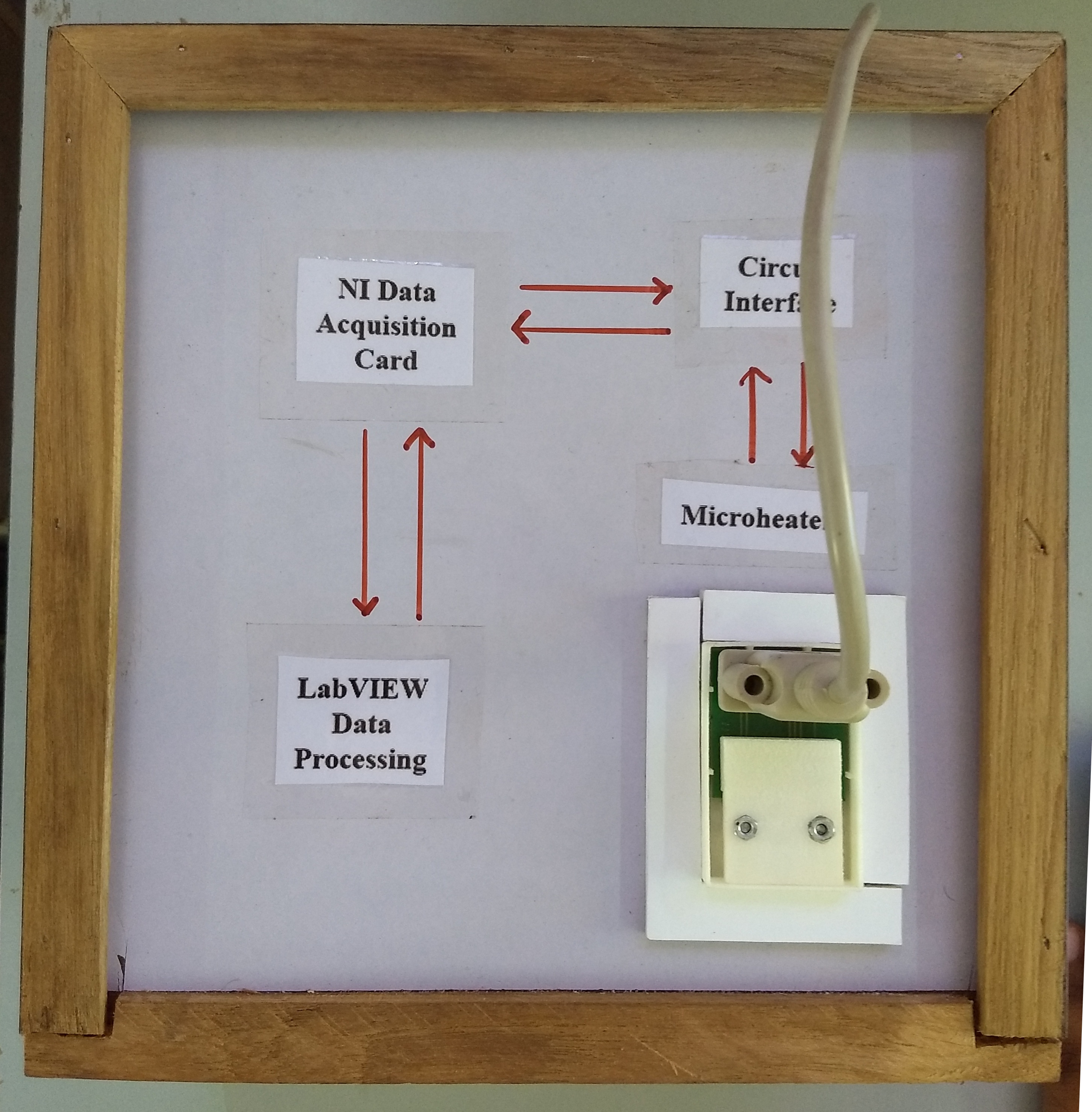
Schematic of Characterization Setup

Microheater - NMH200
NHM200 is a Micro Heater with an integrated temperature sensor. It consists of two suspended and interdigitated platinum coils, viz. Heater and Sensor. The low thermal mass of the heater coil allows for high speed heating and cooling within a few milliseconds. Temperature is sensed by the sensor coil whose resistance increases with temperature in a known and repeatable way. It exhibits very high accuracy over a wide range of temperatures.
LabVIEW
LabVIEW (short for Laboratory Virtual Instrument Engineering Workbench) is a system-design platform and development environment for a visual programming language from National Instruments. LabVIEW programs/subroutines are called virtual instruments (VIs). Each VI has three components: a block diagram, a front panel and a connector panel. The last is used to represent the VI in the block diagrams of other calling VIs. The front panel is built using controls and indicators. Controls are inputs : they allow a user to supply information to the VI. Indicators are outputs : they indicate, or display, the results based on the inputs given to the VI. The back panel, which is a block diagram, contains the graphical source code. All of the objects placed on the front panel will appear on the back panel as terminals. The back panel also contains structures and functions which perform operations on controls and supply data to indicators. The structures and functions are found on the Functions palette and can be placed on the back panel. Thus a virtual instrument can be run as a program with the front panel serving as a user interface. The graphical approach also allows non-programmers to build programs by dragging and dropping virtual representations of lab equipment with which they are already familiar.
NI myDAQ
NI myDAQ is a low-cost data acquisition (DAQ) device that gives user the ability to measure and analyze live signals anywhere, anytime. NI myDAQ is compact and portable so user can extend hands-on learning outside of the lab environment using industry-standard tools and methods.
Calibration: To find the Resistance of RTD coil at Room Temperature and zero degree celcius.
__________________________________________________________________________________________________________________
Experiment1: To measure the temperature of the heated membrane and plot various characteristics for a given DC voltage excitation.
__________________________________________________________________________________________________________________
Experiment2: To measure the temperature of the heated membrane and plot the response for sine, square and triangular waves.
__________________________________________________________________________________________________________________
Go to the Simulator tab for performing the simulation.
NOTE: Before running the simulation, download the LVRTE86min.exe file from NI website from the direct link available through click here to download RTE 8.6 option. You would require your own user login at NI webpage (if you dont have already) for downloading the .exe file. Run the .exe file. Then unzip the .zip file.
The plugins are installed in C:/Programfiles/NationalInstruments/Shared/LabVIEW Run-Time/Current LabVIEW Version8.6/Browser Plugins.
Copy both the Plugins LV86ActiveXControl.dll (for Internet Explorer), nplv86win32.dll (for Mozilla) and paste in respective browser plugins.
(Eg. C://programfiles/Internet Explorer/Plugins and
C://programfiles/Mozilla Firefox/Plugins)
__________________________________________________________________________________________________________________
__________________________________________________________________________________________________________________
__________________________________________________________________________________________________________________
__________________________________________________________________________________________________________________
__________________________________________________________________________________________________________________
__________________________________________________________________________________________________________________
1) Electronics Engineering Department
Bharatiya Vidya Bhavans
Sardar Patel Institute of Technology
Munshi Nagar, Andheri(W), Mumbai-400058
http://etrx.spit.ac.in/
022-26707440
2) Dr. S.S Rathod (Co-guide)
Designation: Professor & HOD, Electronics Engineering Department
Qualification: Ph.D. (IIT Roorkee)
Experience: 20 Years
Expertise: Semiconductor Device Modeling, VLSI Design, Radiation Effects
Email: surendra_rathod@spit.ac.in

3) Prof. P. V. Kasambe (Guide)
Designation: Assistant Professor
Qualification: M.E. (Pursuing Ph.D.)
Experience: 18 Years
Expertise: Control Sys, Instrumentation, Linear IC, MEMS, IC Technology
Email: prashant_kasambe@spit.ac.in
3) Siddhesh Patil
B.E. (Electronics Engineering)
Expertise: LabVIEW Programming, NI myDAQ, Eagle PCB designer, Basic webpage design.
Email: patilsiddhesh2708@gmail.com

4) Chaitanya Shrivardhankar
B.E. (Electronics Engineering)
Expertise: LabVIEW Programming, NI myDAQ, Eagle PCB designer, Basic webpage design.
Email: chait96@gmail.com

4) Sukhadeo Mote
B.E. (Electronics Engineering)
Expertise: LabVIEW Programming, NI myDAQ, Eagle PCB designer, Basic webpage design.
Email: sukhmote1997@gmail.com
