Block Diagram of System
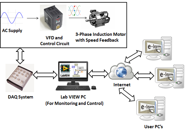
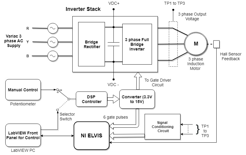
The figure shows us the detailed system block diagram of the project. It includes giving three phase AC supply voltage through VARIAC to the input of the three phase bridge rectifier. The output of the three phase bridge rectifier is given to DC link capacitor for filtering. It acts as an input to the three phase bridge inverter circuit. Three phase bridge inverter circuit requires six gate pulses to be fed at the input of the IGBTs. The gate pulses are provided by DSP controller. The algorithm used for speed control of Induction motor is SVM method. The pulses are then fed to the gate driver circuit, the output of which will drive the gates of six IGBTs to provide the required switching. The six pulses are then viewed on the GUI to determine the phase shift between the pulses and voltage level is also determined. Three phase output voltage of the Inverter is then provided to the three phase Induction motor. Another test point is provided at the motor terminal voltage to measure the phase voltage. The output of the motor terminal voltage is provided at the input of the signal conditioning circuit. The signal conditioning circuit is required to convert the 230V AC output voltage into 1.2V AC voltage. The signal conditioned output is required to display the motor terminal waveform on the GUI. In total three signal conditioning circuits are required to view the waveforms of three phases. One phase is provided between R & Y, one is provided between Y & B and the last one is provided between R & B In order to measure the speed of the Induction motor, Hall Effect sensor is used. The output of the Hall Effect sensor is in the form of the pulses, the pulses are then fed to the counter input of the NI ELVIS II. The counter pulses are converted into its equivalent frequency and the frequency is then multiplied by 60 to determine the speed of the motor in RPM. In order to provide the speed control of Induction Motor through GUI, analog output voltage of NI ELVIS II is required. By varying the analog output voltage of NI ELVIS II, the voltage fed at the ADC input of DSP controller will vary, which will vary the frequency which will in turn vary the speed of Induction motor. This is referred to an auto mode of speed control. Along with speed control of Induction motor through GUI; speed can also be varied with the help of a potentiometer. By varying the potentiometer the voltage fed at the ADC input of DSP controller will vary, which will vary the frequency which will in turn vary the speed of Induction motor. This is referred to an manual mode of speed control. In order to switch between the Auto and the Manual mode of the speed control, a selector switch is used.
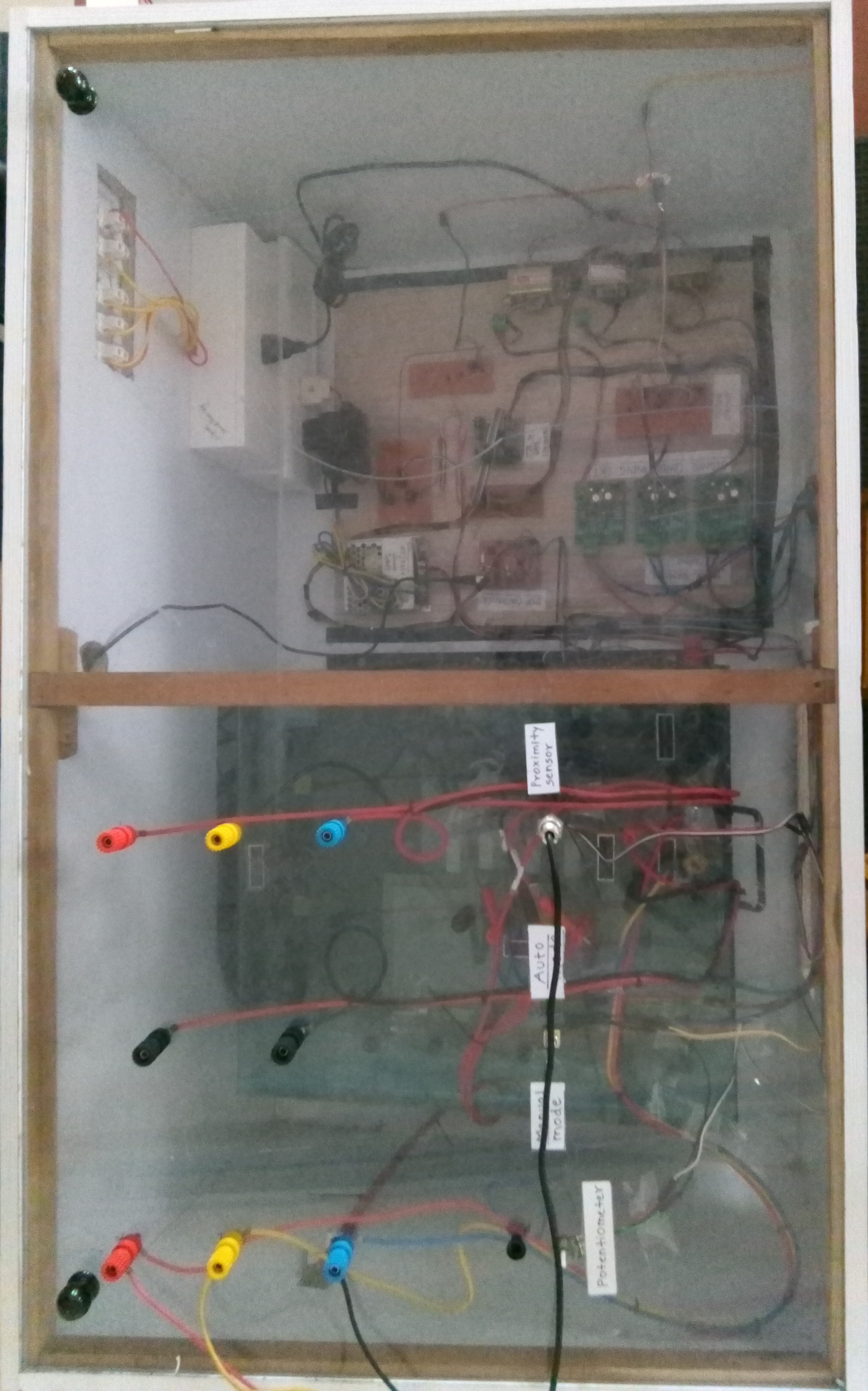
Actual view of VFD Trainer
Schematic of Flow Control Trainer
LabVIEW
LabVIEW (short for Laboratory Virtual Instrument Engineering Workbench) is a system-design platform and development environment for a visual programming language from National Instruments. LabVIEW programs/subroutines are called virtual instruments (VIs). Each VI has three components: a block diagram, a front panel and a connector panel. The last is used to represent the VI in the block diagrams of other calling VIs. The front panel is built using controls and indicators. Controls are inputs that allow a user to supply information to the VI. Indicators are outputs that indicate, or display, the results based on the inputs given to the VI. The back panel, which is a block diagram, contains the graphical source code. All of the objects placed on the front panel will appear on the back panel as terminals. The back panel also contains structures and functions which perform operations on controls and supply data to indicators. The structures and functions are found on the Functions palette and can be placed on the back panel. Thus a virtual instrument can be run as a program with the front panel serving as a user interface. The graphical approach also allows non-programmers to build programs by dragging and dropping virtual representations of lab equipment with which they are already familiar.
NI ELVIS-II
The primary function of the NI ELVIS II board is to sample various signals available at various test points on the Variable Frequency Drive Circuit obtained from signal conditioning circuits. This includes output voltage and the output frequency of the inverter circuit and the output of uncontrolled three phase bridge rectifier circuit. NI ELVIS II feature allows to sample the analog inputs at MHz frequency range and then display them on the PC screen.When NI ELVIS II board is interfaced to the PC, realtime monitoring and control is also possible from a remote location on Internet. For eg. In case of Hall proximity Sensor, the output is in the form of pulses and by determining the frequency of the pulses the speed of the Motor can be determined.Hence, NI Elvis II is used to convert the sensor output into speed(in rpm).This is achieved using digital I/O sampling of NI ELVIS II using LabVIEW Software.
1) Electronics Engineering Department
Bharatiya Vidya Bhavan's
Sardar Patel Institute of Technology
Munshi Nagar, Andheri(W), Mumbai-400058
http://etrx.spit.ac.in/
022-26707440
2) Dr. S.S Rathod
Designation: Professor & HOD, Electronics Engineering Department
Qualification: Ph.D. (IIT Roorkee)
Experience: 18 Years
Expertise: Semiconductor Device Modeling, VLSI Design, Radiation Effects
Email: surendra_rathod@spit.ac.in
3) Prof. P. V. Kasambe
Designation: Assistant Professor
Qualification: M.E. (Pursuing Ph.D.)
Experience: 16 Years
Expertise: Control Sys, Instrumentation, Linear IC, MEMS, IC Technology
Email: prashant_kasambe@spit.ac.in
3) Prof. G. T. Haldankar
Designation: Assistant Professor
Qualification: M.E
Experience: 08 Years
Expertise: BEE, Power Electronics, Electronic Circuit Design, Robotics
Email: g_haldankar@spit.ac.in
4) Kaushal Malaviya
B.E.(Electronics)
Expertise: LabVIEW Programming, PLC Programming, Power Enginnering,
NI myDAQ, Allen Bradley PLC. Power Circuits and Power Electronics
Email:kaushalmalaviya5@gmail.com

5) Shivam Tripathi
B.E.(Electronics)
Expertise: LabVIEW Programming, Embedded Programming, Power Enginnering,
NI myDAQ,Code Composer Studio, Power Circuits, Robotics and Power Electronics
Email:tripathishivam342@gmail.com

6) Nivesh Vaze
B.E.(Electronics)
Expertise: LabVIEW Programming, ARM, Power Enginnering,
NI myDAQ, Programming, Designing of Electronic Circuits Power Circuits and Power Electronics
Email:niveshvaze@gmail.com